Hello! Welcome to the website of Shenzhen Yongquan automation equipment Co., Ltd!
+86 15914079600 / +86 18123878001

 Full set of production equipment for capacitive touch screen

Hello! Welcome to the website of Shenzhen Yongquan automation equipment Co., Ltd!
+86 15914079600 / +86 18123878001
Full set of production equipment for capacitive touch screen
The utility model relates to the field of laminating machines, in particular to a Soft to hard automatic laminating machine.
1. Background technology:
The film laminating machine is also called OCA laminating machine. It is one of the necessary equipment for touch screen production. It is used to attach the polarizer to the glass substrate of the touch screen at a specified angle. The film laminating machine is highly efficient. , The product yield rate is also high. However, some existing film laminating machines directly push the laminating plate downward to achieve the laminating of the polarizer. This laminating method is not high in laminating accuracy, which will affect the laminating The machine’s fit product yield rate.
2. Technical realization elements:
In view of this, the main purpose of the present invention is to provide a Soft to hard automatic laminating machine in view of the shortcomings of the prior art, which can effectively solve the problem of low laminating accuracy of the existing laminating machine.
In order to achieve the above purpose, the present utility model adopts the following technical solutions:
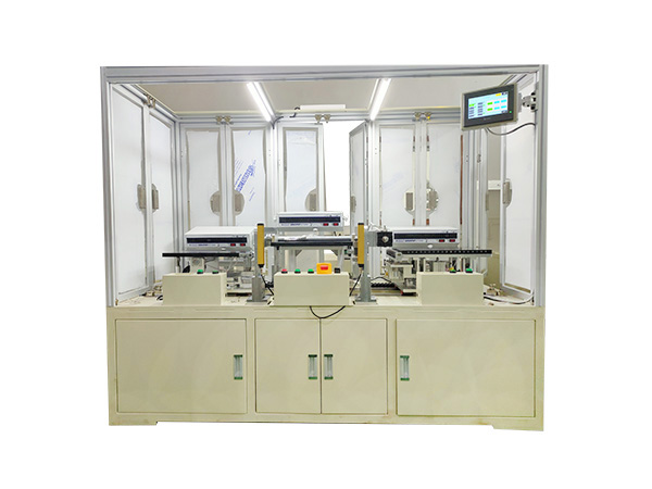
A soft-to-hard laminating machine, including a frame, a linear module, a head suction platform, a movable head, a retracting and unwinding mechanism, a material box, and a film tearing platform; the frame has a workbench and a vertical installation The vertical mounting plate is set on the workbench; the linear module can be movably set on the workbench back and forth; the sticking head suction platform is set on the linear module; the movable sticking head can go up and down and left and right back and forth It is movably arranged on the vertical mounting plate, the movable sticking head is located above the sticking head suction platform, and the moving sticking head has a sticking rubber roller; the retracting and unwinding mechanism, the material box and the film tearing platform are all arranged on the vertical mounting plate On the upper side, the material box and the film tearing platform are located between the movable sticking head and the retracting and unwinding mechanism, and the material box is located above the film tearing platform.
Preferably, the linear module is driven by a servo motor to move back and forth.
Preferably, a dust-removing rubber roller is provided on the worktable, and the dust-removing rubber roller is located above the linear module.
Preferably, the dust removing rubber roller is driven by a cylinder to move up and down.
Preferably, the movable sticking head is driven by a driving mechanism to move up and down and left and right. The driving mechanism includes a horizontal screw rod, a first servo motor, a first sliding seat, a vertical screw rod, a second servo motor, and a second servo motor. Two sliding seats; the horizontal screw, the first servo motor and the first sliding seat are all arranged on the front side of the vertical mounting plate, the first servo motor drives the horizontal screw to rotate, and the horizontal screw drives the first sliding seat left and right Moving back and forth horizontally, the vertical screw, the second servo motor, and the second sliding seat are all arranged on the first sliding seat, the second servo motor drives the vertical screw to rotate, and the vertical screw drives the second sliding seat It moves up and down vertically, and the movable sticking head is arranged on the second sliding seat.
Compared with the prior art, the utility model has obvious advantages and beneficial effects. Specifically, it can be known from the above technical scheme:
By coordinating the installation of the linear module, the head suction platform, the movable head, the retracting and unwinding mechanism, the material box and the film tearing platform, automatic and fast film tearing and filming operations can be realized, and the lamination accuracy is high, which effectively improves the laminating machine Fitting the product yield, the equipment has a simple and compact structure and a reasonable layout.
3. Specific implementation methods
The frame 10 has a workbench 11 and a vertical mounting plate 12, and the vertical mounting plate 12 is arranged on the workbench 11.
The linear module 20 can be movably arranged on the workbench 11 back and forth; in this embodiment, the linear module 20 is driven by the servo motor 21 to move back and forth.
The sticking head suction platform 30 is arranged on the linear module 20; the movable sticking head 40 can be movably arranged on the vertical mounting plate 12 up and down, left and right, and the movable sticking head 40 is located above the sticking head suction platform 30, The movable sticking head 40 has a sticking rubber roller 41; in this embodiment, the movable sticking head 40 is driven by a driving mechanism 80 to move up and down and left and right. The driving mechanism 80 includes a horizontal screw 81, a first servo The motor 82, the first sliding seat 83, the vertical screw 84, the second servo motor 85 and the second sliding seat 86; the horizontal screw 81, the first servo motor 82 and the first sliding seat 83 are all arranged in a vertical installation On the front side of the plate 12, the first servo motor 82 drives the horizontal screw 81 to rotate, the horizontal screw 81 drives the first sliding seat 83 to move back and forth horizontally, the vertical screw 84, the second servo motor 85 and the second The sliding seats 86 are all arranged on the first sliding seat 83, the second servo motor 85 drives the vertical screw 84 to rotate, and the vertical screw 84 drives the second sliding seat 86 to move up and down vertically, the movable sticking head 40 Set on the second sliding seat 86.
The retracting and unwinding mechanism 50, the material box 60 and the film tearing platform 70 are all arranged on the vertical mounting plate 12. The material box 60 and the film tearing platform 70 are all located between the movable sticking head 40 and the retracting and unwinding mechanism 50, and the material The box 60 is located above the tear film platform 70.
And, a dust-removing rubber roller 91 is provided on the worktable 11, and the dust-removing rubber roller 91 is located above the linear module 20, and the dust-removing rubber roller 91 is driven by an air cylinder 92 to move up and down.
When working, the magazine 60 puts multiple membranes into it, and the single-sided adhesiveness of the tape is used to adhere the membranes from the magazine 60. At the same time, the retractable and unwinding mechanism 50 with adjustable tension drives the membrane absorbed on the tape. To the film tearing platform 70 (the receiving shaft 51 is connected to an adjustable tension magnetic powder clutch 52, and the unwinding shaft 53 is connected to an adjustable tension brake 54). After the film is torn, the film is blown to the top suction platform At 30, the small negative pressure absorbs the diaphragm, and uses the X and Y coordinates to clamp to the set position and immediately switches to large negative pressure to absorb the diaphragm. At the same time, the rewinding shaft 51 rotates the waste tape to the shaft. The bonded object is placed on the fixture and is adsorbed by vacuum negative pressure. The servo motor 21 drives the fixture and diaphragm on the linear module 20 to move forward in a straight line. The dust removal rubber roller 91 moves down to the position of the movable stick 40 after removing dust. The movable sticking head 40 presses down, the linear module 20 drives the jig to retreat, and the sticking rubber roller 41 presses down the film and the object to be bonded, so as to achieve the goal of no bubbles and close fit.
The technical principles of the present invention are described above in conjunction with specific embodiments. These descriptions are only for explaining the principles of the present invention, and cannot be interpreted as limiting the protection scope of the present invention in any way. Based on the explanation here, those skilled in the art can think of other specific embodiments of the present invention without creative work, and these methods will fall within the protection scope of the present invention.
Yongquan Automation is a high-tech production enterprise specializing in the research and development, design, production and sales of a full set of production equipment for capacitive touch screens, specializing in the production of laminating equipment, defoaming equipment and hot pressing equipment. To learn more about the Soft to hard automatic laminating machine, please pay attention to Yongquan Information!
Phone
+86-181-2387-8001
+86-181-2392-2059
+86-181-2392-7701
+86-181-2392-7702
+86-181-3843-7707
+86-0755-27616156

WeChat Mini Program
Mobile station
Mobile station
szyqtop@163.com